PAPER DEEP DIVE
Towards Artificial Nerves: Biomimetic Optical-Fiber Tactile Sensing for Robots
Robotic systems increasingly demand tactile sensing that approaches the adaptability and resolution of human skin to enable dexterous manipulation and safe interaction. OptiTac is a biomimetic tactile sensor that emulates the mechanoreceptor-to-nerve architecture of human touch by pairing each mechanical pin on a soft skin with an optical fiber acting as an artificial nerve. This design demonstrates an architectural principle for routing tactile information away from the sensing surface while preserving high spatial resolution, establishing a practical route toward distributed tactile sensing in future robotic systems. By treating tactile signals as images, simple analytical methods, rather than opaque deep-learning models, are used to infer contact location, size, and shape, providing interpretable and scalable tactile intelligence. This work demonstrates how evolutionary principles from biology can guide the development of artificial nerve systems for robots, offering a pathway toward human-like tactile perception in next-generation robotic platforms. More broadly, OptiTac establishes an artificial nerve-inspired sensing framework for interpretable robotic touch and a scalable route toward future distributed tactile systems.
Paper: Towards Artificial Nerves: Biomimetic Optical-Fiber Tactile Sensing for Robots
Authors: Laura E. Butcher, Chris J. Ford, Nathan F. Lepora, Efi Psomopoulou
Affiliation: School of Engineering Mathematics and Technology, University of Bristol, UK
Link: arXiv:2607.15746v1 [cs.RO], July 2026
Code: ❌ No public code released (hardware proof-of-concept paper)
1. Abstract
Robotic systems increasingly demand tactile sensing that approaches the adaptability and resolution of human skin to enable dexterous manipulation and safe interaction. This paper presents OptiTac, a biomimetic tactile sensor that emulates the mechanoreceptor-to-nerve architecture of human touch by pairing each mechanical pin on a soft skin with an optical fiber (OF) acting as an artificial nerve. The design demonstrates an architectural principle for routing tactile information away from the sensing surface while preserving high spatial resolution, establishing a practical route toward distributed tactile sensing in future robotic systems. The key insight: by treating tactile signals as images, simple analytical methods — rather than opaque deep-learning models — are used to infer contact location, size, and shape, providing interpretable and scalable tactile intelligence.
2. Background and Motivation
Human skin is a naturally-evolved tactile sensor that sets the standard for robotic systems. Research estimates approximately 230,000 mechanoreceptors distributed across the skin, with densities of 241, 81, and 58 units/cm² in fingertips, fingers, and palms respectively, compared to only 13 units/cm² in arms. Mechanoreceptors use Merkel cells and Meissner corpuscles as end organs to transduce mechanical tactile information into electrical signals. Nerves transmit tactile information away from the skin to specific spinal cord regions, and projection neurons relay these signals to the somatosensory cortex, where separate regions process information from different skin areas — down to distinct regions for individual fingers.
Pain points in existing tactile sensors:
- Need for low-cost, soft, distributed tactile sensing;
- Traditional vision-based tactile sensors (e.g., TacTip) place cameras directly at the sensing surface, making distributed deployment difficult;
- Deep-learning-based tactile methods are opaque "black boxes," making feature selection unexplainable and hindering calibration, failure analysis, and sensor redesign.
OptiTac's motivation stems from biological evolutionary principles: use an optical fiber array (OFA) to replace biological nerves, physically separating tactile signals from the soft sensing interface to a remote imaging module while preserving TacTip's biomimetic mechanical transduction.
3. Core Method
3.1 Sensor Architecture: Pin-Fiber Biomimetic One-to-One Pairing
OptiTac consists of two physically separated modules:
- Soft sensing module: Multi-material 3D-printed flat tactile skin (Agilus30 black rubber) with biomimetic pins on the inner surface; white markers on pin tips (VeroWhite). Transparent elastomeric gel (TechsiL RTA27905) injected between skin and acrylic window provides compliance and visible light transmission. An LED ring illuminates the white markers.
- Remote imaging module: 217 plastic optical fibers (1 mm diameter, 95 mm length) arranged in a hexagonal array, held flush against the acrylic window. Fibers transmit marker-reflected light to a remote camera (3D-printed casing reduces ambient light).
Upon tactile deformation, the skin indents, pins lever, and white markers align/unalign with OFs: alignment yields high intensity output; misalignment yields low intensity. The camera captures all OF endface light intensities, reconstructing high-resolution surface plots.
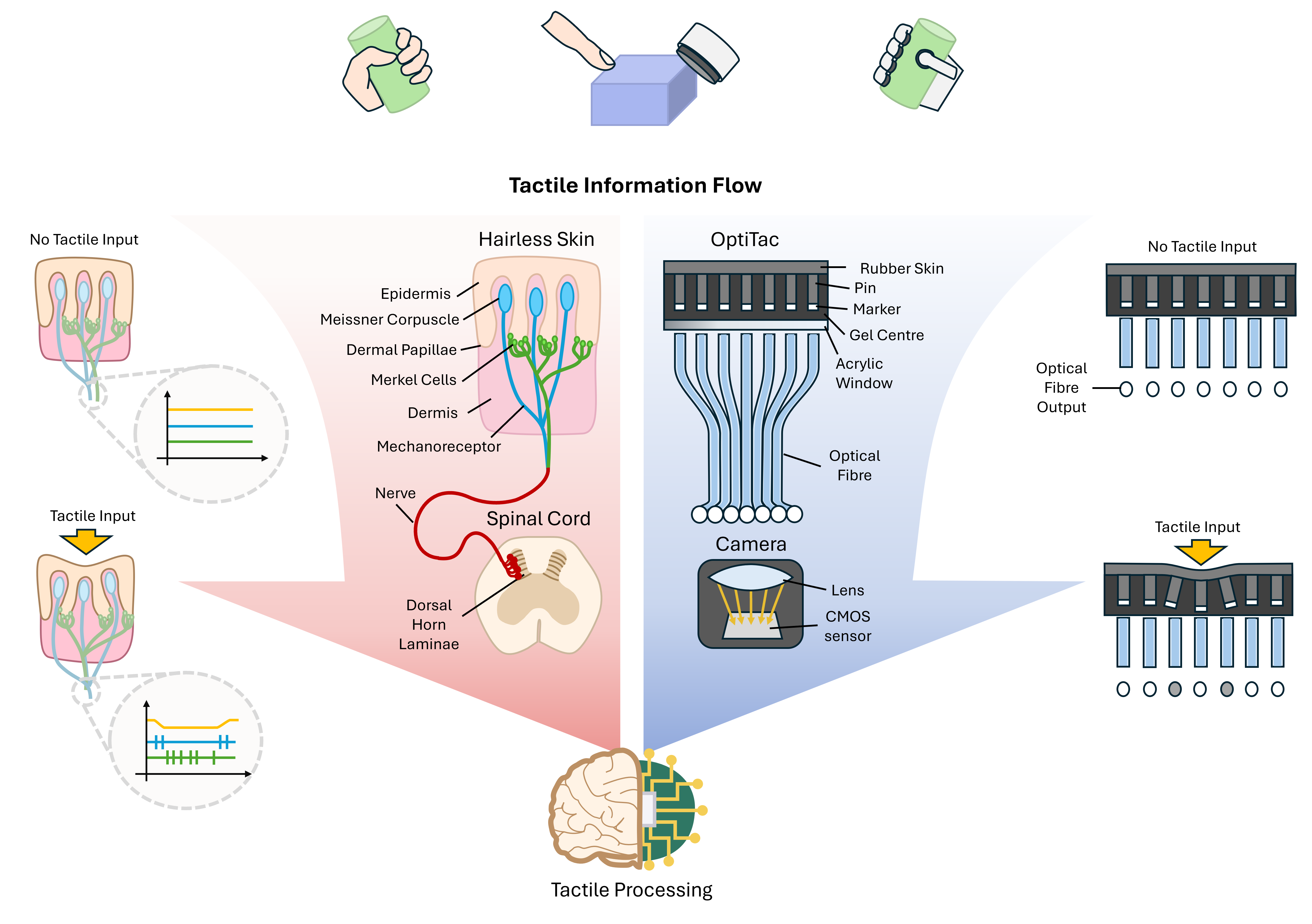
Figure 1: Concept and biomimetic design of the OptiTac tactile sensor. Pins are paired one-to-one with optical fibers, emulating the mechanoreceptor-to-nerve signal transduction architecture.
3.2 Comparative Design of Three Pin Patterns
To design the optimal signal-transmitting skin, the authors fabricated three pin patterns (constant diameter and length, varying only spacing):
| Pattern | Pin Spacing | 5mm Ball Indent 3mm Depth Response |
|---|---|---|
| (i) Sparse | Fewer pins than OFs | Surface-wide intensity changes (markers entering/leaving FOV) |
| (ii) Dense | 2 mm (>1.5mm OF spacing) | More localized but still larger than indenter; complex, non-intuitive pattern |
| (iii) Aligned one-to-one | Each pin vertically aligned with one OF | Localized negative intensity change, intuitive response |
Only the aligned one-to-one pattern produced localized intensity changes — the core design choice of OptiTac, mimicking how Merkel cells/Meissner corpuscles transmit tactile information to mechanoreceptors.
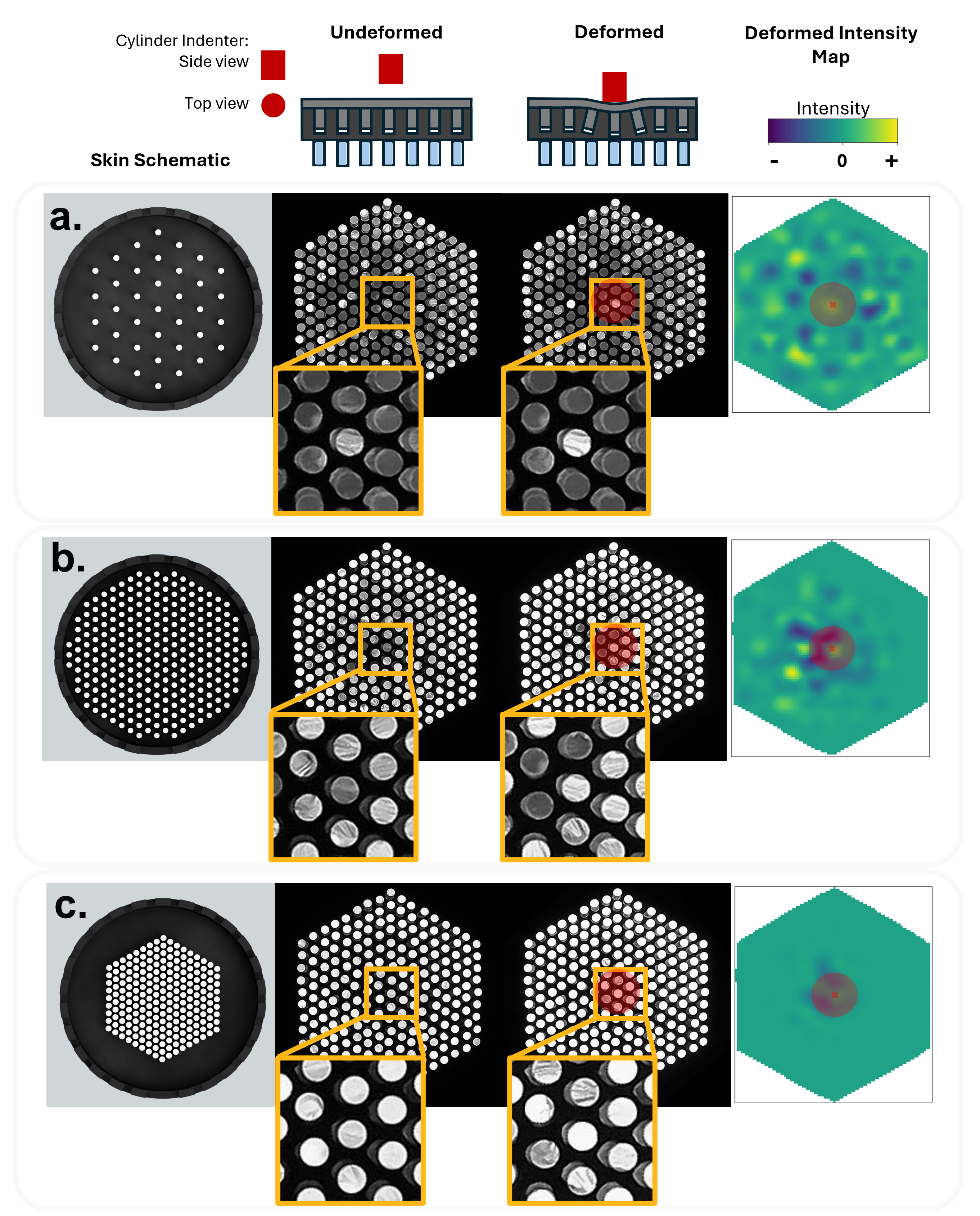
Figure 3: Three pin pattern comparison. Only (iii) aligned one-to-one pattern produces localized, analytically tractable intensity changes.
3.3 Signal Processing Pipeline
Raw camera images are RGB format with large amounts of redundant data. Preprocessing pipeline:
- Grayscale conversion: RGB to single-channel grayscale (markers white, skin black; intensity changes only, no color change);
- Rotation and cropping: Remove non-OFA image pixels;
- OF endface localization: Template matching or brightness peak detection to locate each fiber endface pixel region;
- Pixel averaging: Average all pixels within each OF endface to produce a single intensity value, constructing the tactile surface plot.
flowchart LR
    A[Physical Contact
Skin Deformation] --> B[Pin Levering
White Marker Displacement]
    B --> C[Marker-OF Alignment Change
Light Intensity Modulation]
    C --> D[217 OFs Transmit Light
to Remote Camera]
    D --> E[RGB to Grayscale to Crop
OF Endface Localization]
    E --> F[Pixel Averaging
Generate Tactile Surface Plot]
    F --> G[Image Moment Method
Location + Width + Shape]
    G --> H[Calibration Surface Correction
k-d Tree + Gaussian Filter]
    H --> I[Output: Contact Position/Size/Shape]
3.4 Contact Localization: Image Moments
Using the physically preprocessed tactile image, image moments analytically extract contact location. Ordinary moments:
$$m_{ij}=\sum_{x}\sum_{y}x^{i}y^{j}I(x,y)$$
Contact centroid coordinates:
$$\bar{x}=\frac{m_{10}}{m_{00}}, \quad \bar{y}=\frac{m_{01}}{m_{00}}$$
3.5 Contact Width Estimation: Central Moments and Eigenvalues
Central moments (moments about the distribution mean, location-invariant):
$$\mu_{ij}=\sum_{x}\sum_{y}(x-\bar{x})^{i}(y-\bar{y})^{j}I(x,y)$$
Normalized central moments:
$$\mu_{ij}^{\prime}=\frac{\mu_{ij}}{\mu_{00}}$$
From second-order central moments, contact region eigenvalues:
$$\lambda_{1,2}=\frac{(\mu_{20}^{\prime}+\mu_{02}^{\prime})}{2}\pm\frac{\sqrt{(4\mu_{11}^{\prime 2})+(\mu_{20}^{\prime}-\mu_{02}^{\prime})^{2}}}{2}$$
Assuming Gaussian contact, full width at height $h$ (FWHM):
$$\text{FW}=\text{principle~axes}_{1,2}=2\sqrt{2\ln{h}}\sqrt{\lambda_{1,2}}$$
3.6 Contact Shape Classification: Hu Invariant Moments + GMM
Seven orthogonal invariants (Hu moments) are constructed from second- and third-order central moments for pattern recognition. The paper selects the first three Hu moments as the feature vector:
$$M1=\mu_{20}+\mu_{02}$$
$$M2=(\mu_{20}-\mu_{02})^{2}+4\mu_{11}^{2}$$
$$M3=(\mu_{30}-3\mu_{12})^{2}+(3\mu_{21}-\mu_{03})^{2}$$
After log-transform, a Gaussian Mixture Model (GMM) unsupervised clustering method classifies data points by shape.
3.7 Calibration: k-d Tree + Gaussian Filter
Initial development revealed centroid errors clustered toward the OFA center with larger errors at the periphery. Calibration procedure:
- Collect contact data above each OF (5mm cylindrical indenter) to obtain error distribution;
- Build a k-d tree indexing measured positions;
- Create two 1000×1000 grid meshes for x and y axes (spanning larger than OFA area);
- Perform nearest-neighbor search on meshes, assigning error values from nearest measured position;
- Apply Gaussian filter with σ=10 to smooth region boundaries and prevent overfitting;
- At calibration: round measured centroid to nearest grid value, subtract corresponding error.
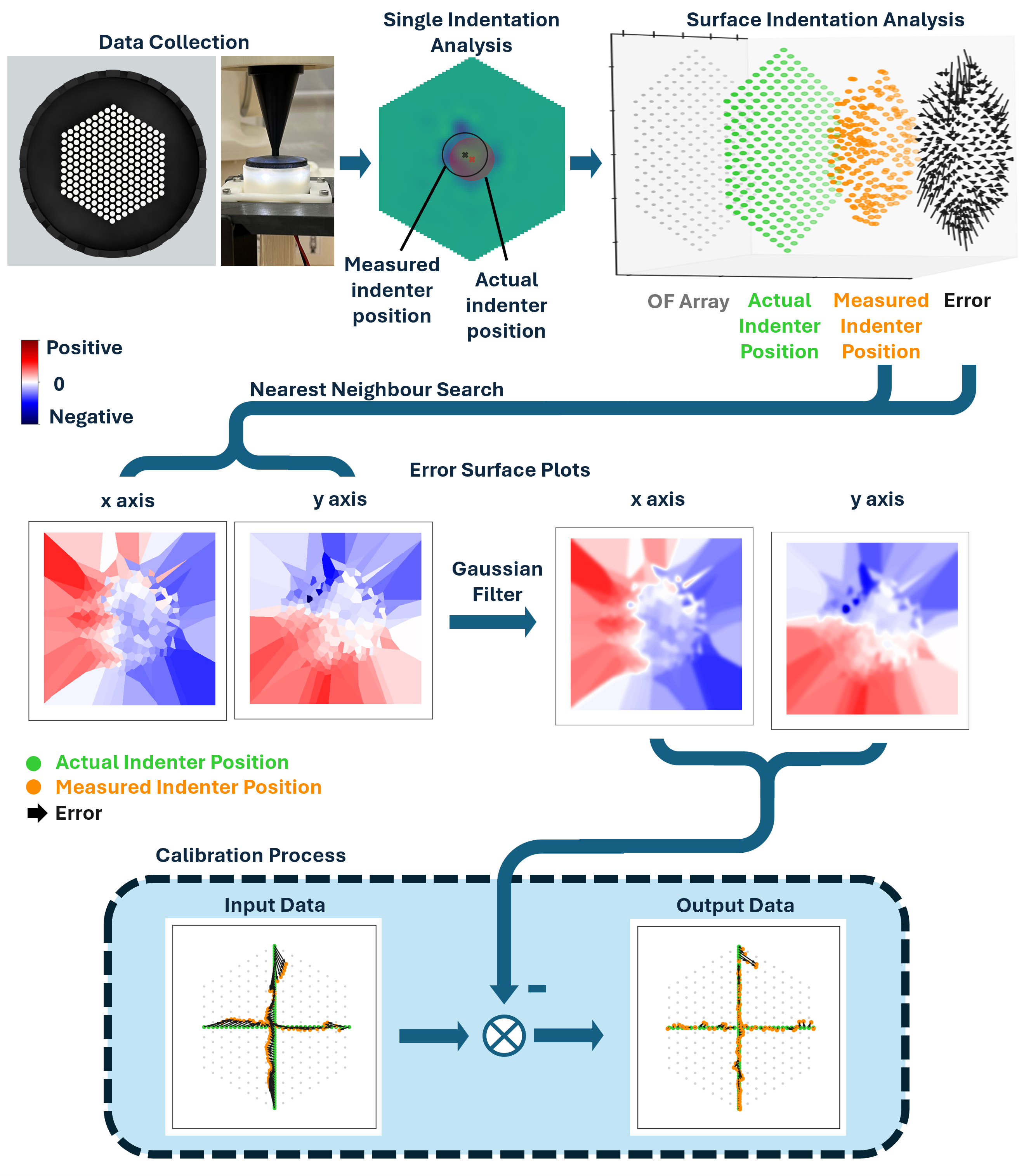
Figure 4: Development of the contact centroid localization calibration method. k-d tree + Gaussian filter generates error surface plots, significantly reducing peripheral errors.
4. Key Experiments
4.1 Contact Centroid Localization Accuracy
An ABB IRB 120-3/0.6 robot arm performed indentations at various locations (3mm depth). Two datasets evaluated calibration:
- "Seen" dataset: Data used to generate calibration surface plots (indentations aligned with each OF)
- "Unseen" dataset: Incremental indentations between neighboring OFs along x/y axes
| Dataset | R² | RMSE | Notes |
|---|---|---|---|
| Seen (calibrated) | 0.99 | Reduced by 0.26 mm | Gaussian filter prevents overfitting |
| Unseen (calibrated) | 0.99 | 0.4 mm (x/y axes) | Validates inter-OF interpolation |
Hyperacuity: Centroid measurement precision is more than 3× smaller than the spacing between neighboring pin-OF pairs — sub-millimeter localization, far exceeding the 1.5mm fiber spacing.
4.2 Comparison with Existing OFA Tactile Sensors
| Sensor | OF Spacing | Method | x RMSE | y RMSE |
|---|---|---|---|---|
| Baimukashev et al. (2020) | 3.9 mm | Multi-output CNN | 1.1 mm | 1.4 mm |
| Lu et al. (2023) | 3.9 mm | Multiscale ResNet | 0.03 mm | 0.02 mm |
| OptiTac (this work) | 1.5 mm | Image moments (analytical) | ~1 mm | ~1 mm |
OptiTac achieves sub-millimeter localization with a transparent analytical pipeline, demonstrating that physically structured tactile sensing can approach useful performance without requiring end-to-end deep learning.
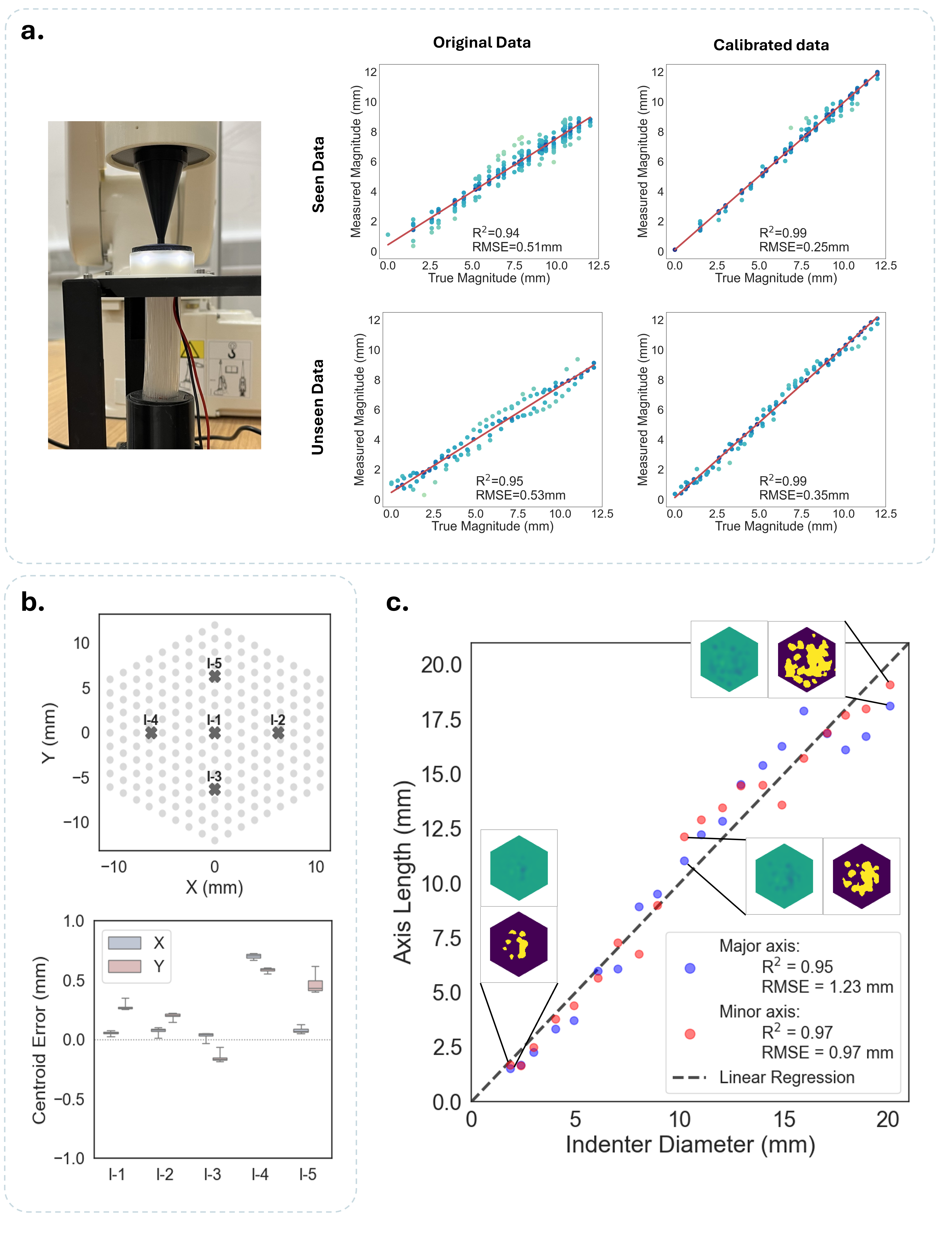
Figure 5: Tactile contact characterization. Calibrated centroid localization, repeatability test, and contact width estimation results.
4.3 Repeatability Test
10 indentations at each of 5 locations (5mm flat circular indenter, 3mm depth). Due to hexagonal array causing different x/y OF spacing, axes were analyzed separately:
Average centroid errors at all five locations were less than ±0.71 mm, further demonstrating hyperacuity.
4.4 Contact Width Estimation
Circular indenters from 1.85–20.09 mm diameter (Stratasys F370 printed) indented 3.0mm; major and minor axes measured. Lower bound 1.85mm limited by printer resolution; upper bound 20.09mm ensures local deformation stays within OFA bounds.
4.5 Shape Classification
Using the first three Hu moments (M1, M2, M3) as feature vector, average diagonal element value was 96%. GMM classification results:
| Shape | True Positive | False Positive | F1 Score |
|---|---|---|---|
| Edge | — | — | 1.00 |
| Square | 100% | Non-zero | ≥0.90 |
| Triangle | 100% | Non-zero | ≥0.90 |
All shapes had a minimum F1-score of 0.90. Edge F1=1.00 indicates highly distinctive features. Non-zero false positives for square/triangle arise from GMM statistical clustering overlap when shapes produce similar feature distributions.
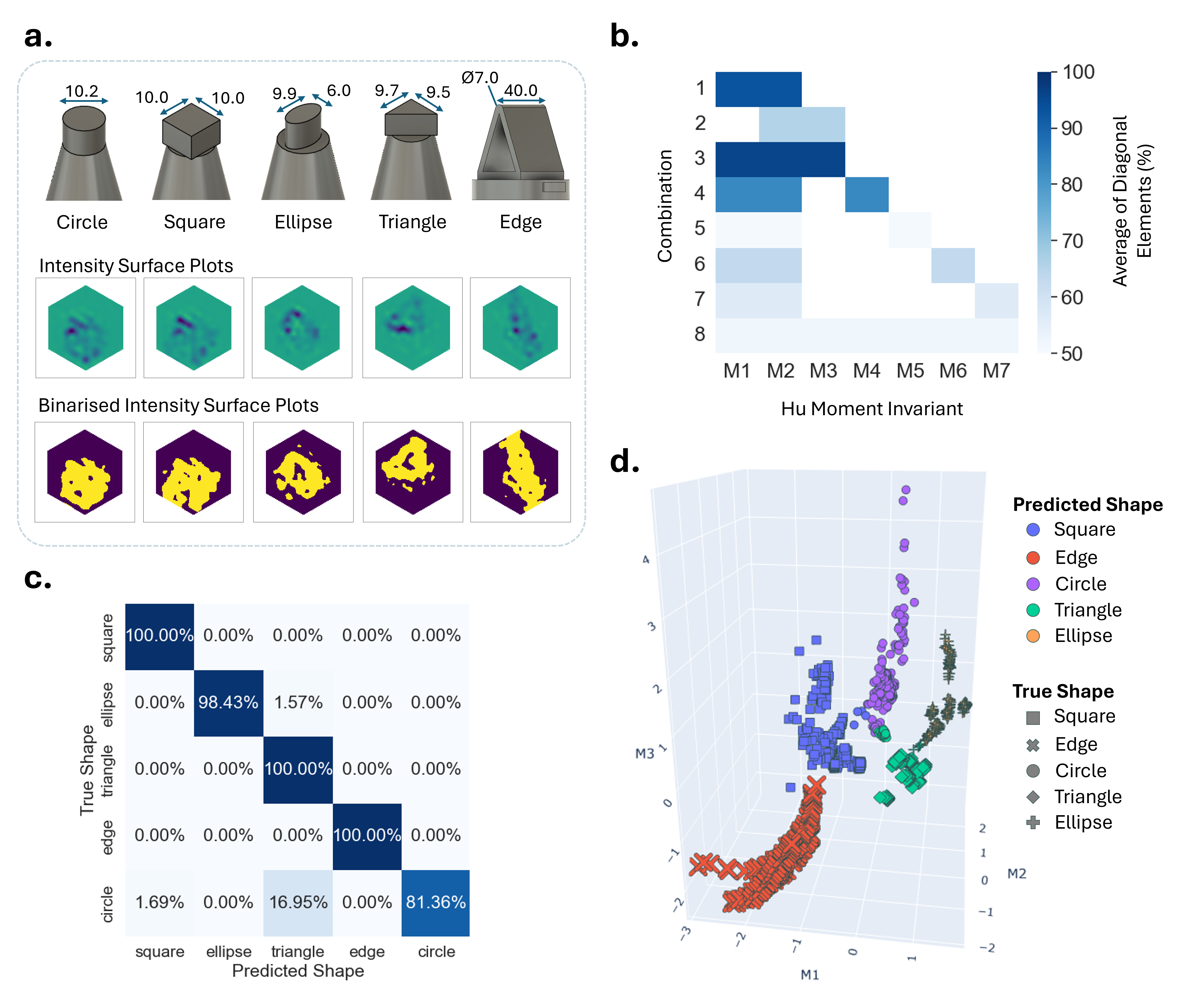
Figure 6: Contact shape classification using OptiTac. GMM clusters in Hu moment feature space are clearly separable.
5. Limitations and Future Work
- OF endface pixel averaging loses spatial information: All pixels within each OF endface are averaged; spatial information mixed within an OF is lost. Deep-learning methods using raw OFA images retain this information.
- Limited calibration points: Calibration collected only directly above OFs; future work will extend to arbitrary contact distributions and broader operating conditions.
- Controlled lab conditions: Short fibers, fixed packaging. Future work must quantify robustness under longer fiber routing, repeated bending, packaging tolerances, and environmental variation.
- Simple feature descriptors: Only Hu moments + GMM; generalizability is limited. More advanced feature descriptors could be considered for broader object generalization.
- LED ring retained: Inherited from TacTip design for optimal lighting; future designs could remove it to further miniaturize the sensor.
6. Conclusion
OptiTac evolves the standard TacTip design by integrating a biomimetic optical fiber array (OFA), pioneering a sensor architecture that physically separates tactile information from the sensing surface to a remote imaging module. The biomimetic one-to-one pin-OF pairing enables physical pre-processing, allowing simple image moment analytical methods (rather than deep-learning black boxes) to infer contact location, size, and shape. After calibration, the sensor achieves sub-millimeter localization (R²=0.99, RMSE~0.4mm) while retaining hyperacuity; Hu moments + GMM achieve interpretable shape classification (F1≥0.90). This design principle provides a scalable, interpretable path toward future distributed robotic tactile sensing systems — using "artificial nerves" to replace biological nerves and physically decouple sensing from processing.
SOURCE LINKS