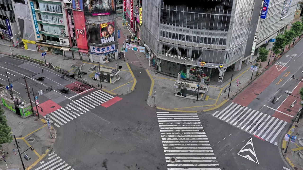
Setting Up a 3DGS Simulation Environment for Isaac Sim: Untouched Scan Data, Ground-Hole Patches, and a PhysX Vehicle in Three Steps
Using Shibuya's scramble crossing as a case study: keep the scanner's 3DGS and mesh untouched, patch only the ground holes from measured LiDAR, stack appearance and physics as two layers, and drive a PhysX Vehicle in Isaac Sim.
Pipeline at a glance: untouched 3DGS scan → load into Isaac Sim → patch only the ground holes → drive on a two-layer stack.
What this article gives you. The inputs are the three standard outputs of a LiDAR-fusion scanner: the 3DGS, the scanner-native mesh, and the dense LiDAR point cloud. (The procedure does not apply to 3DGS reconstructed from cameras alone.) With ground-hole patching as the only post-processing step, you get a two-layer environment — a visible 3DGS stacked on an invisible collider — ready for robot driving, collision, and sensor validation in Isaac Sim. The only dependencies are Python, a point-cloud processing library, and Isaac Sim itself.
The Big Picture: Why a Collider at All
3DGS is unbeatable at looking right. But that is the result of optimising to match photographs — it is not the same thing as the geometry being correct. Used raw in simulation, two failure modes follow.
The first is floaters: gaussians left where nothing exists land in the robot's camera as view noise. This article's policy is to accept them rather than delete them, because deletion passes keep destroying real content (see the optional cleanup section below).
The second is the real wall: holes in collision. 3DGS has no surfaces, so collision must come from the scanner-native mesh — but that mesh's boundary-edge holes (edges not closed by any face) amount to 4.86% in an indoor meeting-room scan and 9.01% in Shibuya. Put a robot on top of a hole, and this happens:
The architecture that fixes both problems is a two-layer structure: a 3DGS layer for appearance, and an invisible collider for physics. NVIDIA × Niantic have published a pipeline of the same shape that constrains geometry with AI-estimated depth — but that is what you do when a 360° camera is all you have. If you already hold measured LiDAR depth, you need neither the depth estimator nor any retraining: the steps below build the same thing, and the authors' validation data includes a quantitative comparison against learned methods.
STEP 1: Loading the 3DGS into Isaac Sim
Convert the 3DGS PLY to USD (in ParticleField form) and load it; the basic conversion and import workflow is covered in the authors' companion article. For a working setup, defuse two traps first:
- Align the coordinate frame. A Y-up 3DGS (e.g. exported from LCC2) only needs a −90° rotation about the X axis after referencing to stand it up — no re-export of the data is required.
- Pin the renderer to RaytracedLighting before opening the stage. Path-tracing modes blow the self-emissive 3DGS out to white, and switching render modes after a 10-million-gaussian scene is loaded is a reliable way to crash. Set it before import, always.
The unit trap when placing robots. Reference assets authored in centimetres — Isaac's stock forklift among them — get an automatic 0.01 correction scale from Kit. But rebuild the xform with
ClearXformOpOrderand that correction disappears — enter a 370-metre forklift. After rebuilding an xform, set scale 0.01 explicitly.
STEP 2: Patching Only the Ground Holes in the Mesh
Use the raw scanner mesh untouched as the collider. The intuitive alternatives both failed in practice: a voxel-hole-filled watertight shell melts the geometry into a "melted wax" shape, and patches cut from such a shell leave spiky fragments. For thin poles and bollards alike, the raw mesh is the most accurate shape information you have.
The only addition is a ground patch: build a smooth ground field from the measured LiDAR surface on a 25 cm grid, then lay faces at field height only in cells where the raw mesh has no ground at all. Holes in walls and building facades never affect driving, so they are left alone. For the Shibuya scan this yields 514k raw + 114k patch = 628k triangles, with zero leaks in the vertical ray test over the drivable area. Only the holes a robot could fall through are sealed — not a single other triangle changes.
STEP 3: Stacking the Two Layers and Driving
Assemble a single USD: define a physicsScene on a Z-up stage; reference the 3DGS file as-is and stand it up with a −90° X rotation (no baked re-export needed); embed the collider as a Mesh, apply CollisionAPI with approximation=none, and call MakeInvisible on it. That completes the two-layer environment: untouched 3DGS for appearance, raw mesh plus ground patches for physics.
The vehicle is built with PhysX Vehicle (omni.physx.vehicle). The wizard API (VehicleData + create_vehicle) generates a four-wheel car with sprung suspension and Ackermann steering in a few lines, driven by just two values: accelerator (0–1) and steer (−1 to 1). The suspension absorbs the raw scan road's small bumps, so the ride stays smooth without smoothing the data. Two traps here: set rootVehiclePath and rootSharedPath explicitly on VehicleData, and register your collider into the generated GroundSurfaceCollisionGroup.
Optional: Cleaning Up With Care
Deleting floaters and scanned-in pedestrians in post-processing is possible, but deletion passes readily take real content — poles, signs, bollards — with them, so this procedure uses none. If you must clean up, keep three rules: merge the raw LiDAR cloud into the reference surface; delete by silhouette rather than by rectangles; and after every pass, compare before/after renders from the same viewpoint and visually account for everything that disappeared. For collision and path-planning work, not deleting is the safest option.
Summary
Turning a LiDAR-fusion scanner's 3DGS into an Isaac Sim simulation environment fits in three lines:
- STEP 1: reference the 3DGS untouched, stand it up with a −90° X rotation, and pin the renderer to RaytracedLighting before loading.
- STEP 2: collider = untouched raw mesh + ground-hole patches only (628k triangles and zero drivable-area leaks in Shibuya). Wall holes stay.
- STEP 3: stack the two layers in one USD, make the collider invisible, and drive a PhysX Vehicle with real suspension. No deletion passes, no retraining.
Only two limits are worth remembering: no surface exists where the LiDAR never looked, so keep driving routes inside the observed region; and under the untouched policy, scanned-in pedestrians and parked vehicles remain as real obstacles.
The basics of loading 3DGS into Isaac Sim are covered in the authors' companion article on importing 3DGS into Isaac Sim.
Source: LocaHun 3D Tech Blog — Isaac Sim けに3DGSシミュレーション をセットアップする
Source:LocaHun 3D 技术博客https://web.locahun3d.com/works/3dgs-lidar-denoise.html