PAPER DEEP DIVE
Autonomous Grasping On Quadruped Robot With Task Level Interaction
Quadruped robots are increasingly used in various applications due to their high mobility and ability to operate in diverse terrains. However, most available quadruped robots are primarily focused on mobility without object manipulation capabilities. Equipping a quadruped robot with a robotic arm and gripper introduces a challenge in manual control, especially in remote scenarios that require complex commands. This research aims to develop an autonomous grasping system on a quadruped robot using a task-level interaction approach. The system includes hardware integration of a robotic arm and gripper onto the quadruped robot's body, a layered control system designed using ROS, and a web-based interface for human-robot interaction. The robot is capable of autonomously performing tasks such as navigation, object detection, and grasping using GraspNet. Testing was conducted through real-world scenarios to evaluate navigation, object selection and grasping, and user experience. The results show that the robot can perform tasks accurately and consistently, achieving a grasping success rate of 75 % from 12 trials. Therefore, the system demonstrates significant potential in enhancing the capabilities of quadruped robots as service robots in real-world environments.
Autonomous Grasping on Quadruped Robot with Task-Level Interaction
Paper: Autonomous Grasping On Quadruped Robot With Task Level Interaction
Authors: Muhtadin, Mochammad Hilmi Rusydiansyah, Mauridhi Hery Purnomo, I Ketut Eddy Purnama, Chastine Fatichah
Affiliation: Department of Electrical Engineering / Computer Engineering / Informatics, Institut Teknologi Sepuluh Nopember (ITS), Surabaya, Indonesia
Link: arXiv:2512.01052
One-Sentence Summary
This paper integrates an OpenManipulator-X robotic arm with gripper onto a DeepRobotics Lite3 quadruped robot, achieving task-level human-robot interaction through a layered ROS architecture and finite state machine — the operator simply selects a target room and clicks on a target object via a web interface, and the robot autonomously completes navigation, YOLOv8 object detection, GraspNet grasp pose planning, and execution. A three-stage filtering strategy selects the optimal grasp from numerous candidates, achieving a 75% grasping success rate across 12 real-world trials.
Research Background and Motivation
Quadruped robots have garnered growing attention as versatile solutions in complex environments. The four-legged structure offers better stability than bipedal robots and greater mobility over uneven terrain compared to wheeled robots, emulating the locomotion of animals like dogs or horses. However, most commercial quadruped robots lack manipulation capabilities — they serve solely as mobile platforms for monitoring or exploration, equipped with perception systems for navigation and environmental awareness but without actuators like robotic arms or grippers for physical interaction. This significantly limits their potential as service robots.
Integrating manipulators onto quadruped robots introduces substantial control challenges, especially in remote operation scenarios. The operator must simultaneously manage locomotion and precise arm movements. This complexity is amplified by viewpoint discrepancies between the operator and the robot's surroundings — the operator judges object positions and orientations through limited visual feedback, prone to errors, while communication latency further reduces control effectiveness. Therefore, quadruped robots with integrated manipulators require more advanced automated control systems to ensure intuitive, efficient, and reliable environmental interaction.
The core design philosophy of this paper is task-level interaction — the operator does not directly control robot joints or movement speed but provides high-level task commands (e.g., "go to the bedroom," "grab that charger"), which the robot autonomously decomposes and executes. This design frees the operator from low-level control, allowing focus on task objectives rather than movement details, significantly reducing cognitive load and error rates in remote operation. The approach builds on Zhang et al.'s task-level HRI system and Wanyan et al.'s YOLO-GraspNet architecture, but constructs a complete autonomous pipeline from navigation to grasping on this foundation.
Hardware System Design
The system consists of two subsystems coordinated by a central Perception Host. The quadruped side employs the DeepRobotics Lite3 platform, with a Motion Host powered by an ARM RK3588 processor managing leg motor actuation and sensor communication. The sensor configuration includes: a wide-angle camera for environmental exploration, an Intel RealSense D435i depth camera for depth-based navigation, an ultrasonic radar via UART for proximity sensing, and a LiDAR sensor via Ethernet for 360° mapping and obstacle avoidance. The arm side employs the OpenManipulator-X, a modular arm driven by Dynamixel smart actuators providing high-precision integrated position control and serial communication, controlled by an OpenCR board. The arm's end-effector is also equipped with an Intel RealSense D435i depth camera for 3D visual perception during manipulation. Both subsystems are coordinated by an NVIDIA Jetson Orin NX Perception Host — a module designed for edge AI applications, supporting deep learning inference and real-time robotic control. The mounting bracket was designed using Onshape CAD software and fabricated with a 3D printer.
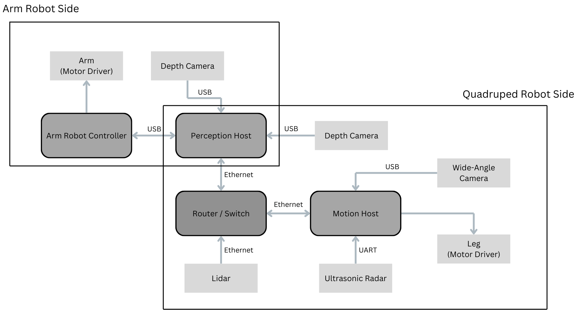
Figure 1: Hardware system architecture. The Perception Host (Jetson Orin NX) centrally coordinates the quadruped side (Lite3 + RK3588) and the arm side (OpenManipulator-X + OpenCR).
User Interface Design
The user interface is implemented as a web dashboard via a ROS WebSocket bridge, requiring no dedicated software installation. The interface provides dual live video streams: the quadruped front camera (left) and the arm end-effector gripper camera (right). A toggle switch at the top activates YOLOv8 object detection, overlaying bounding boxes on detected objects in real time. A status panel displays the robot's current condition (scanning, tracking, grasping, etc.). The lower section is organized into three functional blocks: the left block allows target room selection via a dropdown menu with a "Go" button to initiate navigation; the middle block shows the robot's current location with "Begin Scan" and "Stop" buttons for circular search control; the right block provides real-time operational status indicating whether the robot is searching, has detected the target object, or is performing specific tasks. This layout ensures intuitive control and monitoring aligned with the task-level architecture.
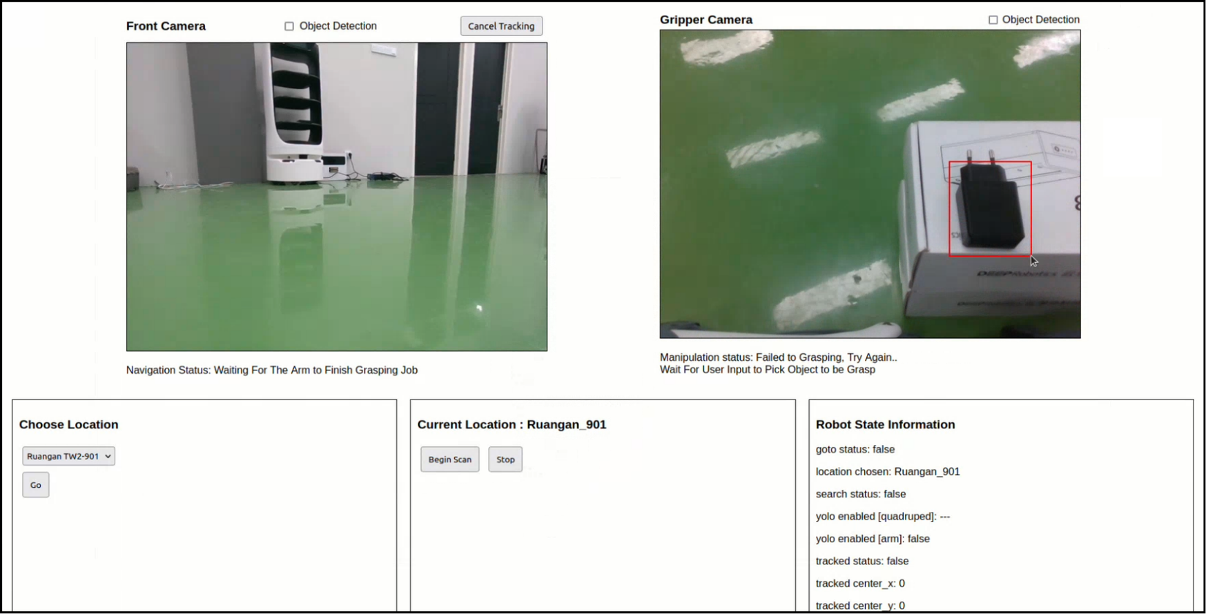
Figure 2: Web interface. Users can select target rooms, monitor location, control search actions, and view live video streams and operational status.
Finite State Machine Workflow
The system decomposes the complete task into structured phases through a finite state machine (FSM), modularly coordinating navigation and manipulation actions while maintaining user interaction flexibility at each state. The FSM structure enables the robot to follow a systematic sequential workflow while preserving user control at key stages, both simplifying system coordination and providing adaptability for complex dynamic real-world scenarios. The specific execution steps are: (1) the robot autonomously navigates from the initial point to the user-selected target room; (2) the robot scans the room to detect objects, the user selects one, and the robot approaches and sits beside it; (3) using the arm-mounted camera, the user selects a specific object for grasping, triggering the arm to execute the grasping operation; (4) the robot transports the grasped object back to the initial point and places it at the designated location.
flowchart TD
  A["Initial Position"] --> B["Autonomous Navigation to Target Room
(LiDAR SLAM + Nav Stack)"]
  B --> C["Circular Scan for Object Detection
(YOLOv8n)"]
  C --> D["User Selects Target Object"]
  D --> E["Approach Object and Sit Down
(PID Controller + CSRT Tracker)"]
  E --> F["Arm Camera Detects Objects
(YOLOv8n)"]
  F --> G["User Clicks to Select Object"]
  G --> H["GraspNet Generates Grasp Candidates"]
  H --> I["Three-Stage Filtering for Optimal Grasp"]
  I --> J["Coordinate Frame Transformation
(Camera Frame to Robot Base Frame)"]
  J --> K["Motion Planning and Grasp Execution"]
  K --> L["Transport Object to Initial Point"]
  L --> M["Place Object"]
Navigation System
Mapping and localization utilize hdl_graph_slam and hdl_localization proposed by Koide et al., based on LiDAR point cloud data. The navigation system integrates object detection and tracking as the basis for movement decisions. Object detection is performed using the YOLOv8n model, enabling real-time recognition of multiple objects from RGB camera frames. Users can select the target object either by clicking or drag-selecting (drag-select handles detection inconsistencies), after which the system switches from detection to tracking mode using cv2.TrackerCSRT_create(), which is robust to scale variation and partial occlusion. Real-time path planning and obstacle avoidance are managed by the ROS Navigation Stack, while a PID controller adjusts linear and angular velocities based on visual feedback (x and distance errors) from the tracker. The outcome is the robot positioned in close proximity to the selected object in a seated posture, considered optimal for manipulation tasks.
The PID controller's control law is:
$$v(t) = K_p \, e(t) + K_i \int_0^t e(\tau)\,d\tau + K_d \frac{de(t)}{dt}$$where $e(t)$ is the lateral deviation and distance error between the target object center and the image center in the current frame, and $K_p$, $K_i$, $K_d$ are the proportional, integral, and derivative gains respectively. Linear and angular velocities are adjusted in real time according to this control law, driving the robot toward the target object while maintaining appropriate distance.
Manipulation (Grasping) System
Once the quadruped robot completes navigation and positions itself in a seated posture near the target object, the manipulation process begins. The robotic arm first moves to its highest reachable position, enabling a wider camera field of view. The onboard camera then streams RGB video, upon which the YOLOv8n model is applied to detect surrounding objects. Detected objects are enclosed in bounding boxes, and users may select a specific object by directly clicking on it. A drag-select feature is also provided — users draw a rectangular region around the desired object, and the system confirms the selection through a pop-up notification, allowing retries until the intended object is accurately highlighted.
Upon confirming the selected object, the system captures and stores three essential input files: the RGB color frame, the aligned depth frame, and the intrinsic camera matrix. These inputs are prerequisites for generating grasp candidates using the GraspNet framework. Notably, GraspNet operates agnostically to object identity and location — it generates grasp poses across the entire input scene. To ensure grasp poses are generated only around the selected object, a masking process is applied: only pixels within the selected bounding box are retained, focusing GraspNet exclusively on the target object. The color frame, depth frame, and camera matrix are then passed into GraspNet, which outputs a set of grasp candidates, each consisting of pose parameters and grasp quality metrics.
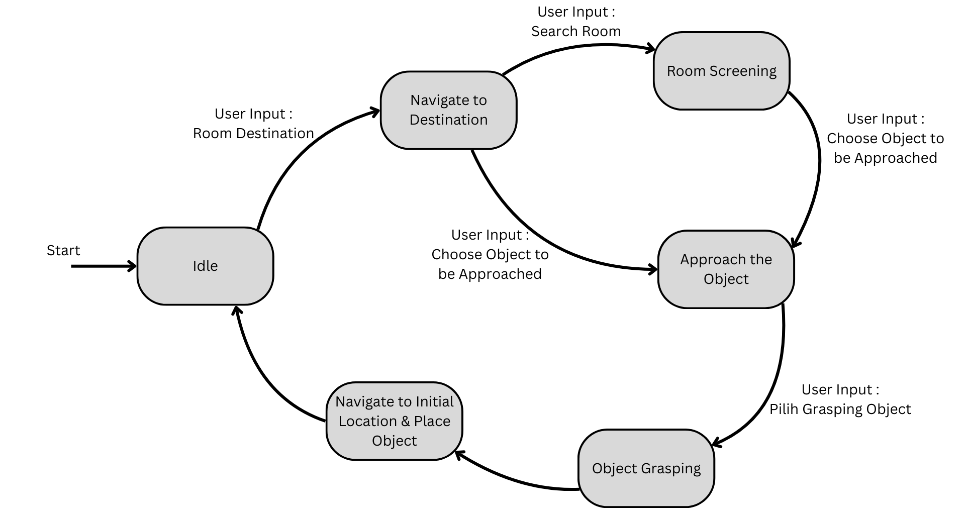
Figure 3: Grasp pose filtering process. GraspNet generates numerous candidate grasp poses, and a three-stage filtering strategy selects the optimal pose for execution.
Three-Stage Grasp Pose Filtering Strategy
From the numerous grasp poses generated by GraspNet, only a single optimal grasp is selected for execution. This requires a filtering process to identify the most feasible and reliable grasp configuration for the robotic arm.
Stage 1 — Confidence Score. The confidence score reflects the probability of successful grasp execution based on the object's geometric structure and the GraspNet deep learning model's prediction output. A higher score indicates a higher probability that the gripper can stably grasp the object without slipping, missing, or destabilizing it. The top 20 grasp poses with the highest confidence scores are selected, effectively eliminating low-confidence candidates. The GraspNet confidence score can be expressed as:
$$S_{grasp} = f_\theta\!\left(P_{scene},\, D_{aligned}\right)$$where $f_\theta$ is the GraspNet deep learning model, $P_{scene}$ is the scene point cloud, and $D_{aligned}$ is the aligned depth map. The model outputs a confidence score $S_{grasp} \in [0,1]$ for each candidate grasp.
Stage 2 — Distance to Object Center. In precision grasping, poses deviating significantly from the object's center of mass are likely to result in unbalanced or unstable grasps. Among the remaining candidates, the pose closest to the object's center point is selected, ensuring a more physically secure and symmetrical grasp location. The distance metric is:
$$d = \left\| \mathbf{p}_{grasp} - \mathbf{p}_{center} \right\|_2$$where $\mathbf{p}_{grasp}$ is the position of the candidate grasp pose, and $\mathbf{p}_{center}$ is the center point of the selected object (computed from the bounding box). The candidate with minimum $d$ is selected.
Stage 3 — Orientation Adjustment. Although GraspNet outputs a full 6-DOF pose, the orientation might not be immediately feasible due to the kinematic limits or joint configurations of the manipulator. Therefore, a rotation is applied to the selected grasp pose matrix to transform it into a reachable and executable orientation, avoiding extreme joint angles or motion discontinuities. The rotation matrix transformation is:
$$\mathbf{T}_{adjusted} = \mathbf{R}_{adj} \cdot \mathbf{T}_{grasp}$$where $\mathbf{T}_{grasp}$ is the original grasp pose from GraspNet (a 4×4 homogeneous transformation matrix), and $\mathbf{R}_{adj}$ is the adjustment rotation matrix computed based on the manipulator's kinematic constraints. Through three-stage filtering, the system identifies a single, high-confidence grasp pose that is both physically feasible and optimal in terms of grasp stability.
Coordinate Frame Transformation
The grasping pose estimated by GraspNet is defined relative to the camera frame, not the robot's frame. The position and orientation — comprising translation and rotation values — are provided in the camera's coordinate system, with the origin at the camera lens and axes aligned to the camera's orientation. While useful for interpreting the object's spatial properties from the camera's perspective, this representation is insufficient for direct use in robotic motion execution. To enable robotic manipulation, a transformation is required to convert the grasping pose from the camera frame to the robot's base (world) frame:
$$\mathbf{T}_{base}^{grasp} = \mathbf{T}_{base}^{camera} \cdot \mathbf{T}_{camera}^{grasp}$$where $\mathbf{T}_{camera}^{grasp}$ is the grasp pose output by GraspNet (in the camera frame), and $\mathbf{T}_{base}^{camera}$ is the camera's pose relative to the robot base (determined by the manipulator's kinematic model). This transformation incorporates both translation and rotation to accurately represent the camera's position and orientation with respect to the robot. The transformed pose data is then passed to the motion planning module, which generates a trajectory for the manipulator to reach and execute the grasping task.
Experimental Results
To validate the proposed system and evaluate its performance in real-world scenarios, a series of experiments involving both navigation and object manipulation tasks were conducted. The experiments were designed to demonstrate how the integrated system — comprising object detection, autonomous navigation, visual tracking, grasp planning, and motion execution — functions cohesively in completing tasks from user instruction to object delivery.
In the evaluation of the robot's movement in approaching objects, the object's position relative to the robot varied but remained within a relatively close range, allowing for successful manipulation. The measured final position values indicated that the object was generally located in front of and slightly to the right of the robot, with coordinates ranging from (24 cm, 5 cm) to (27 cm, 16 cm). The distance from the robot to the object, calculated from the final (x, y) positions, ranged between 24.52 cm and 33.42 cm.
| Trial | Object | Selection Method | Duration | Grasp Status |
|---|---|---|---|---|
| 1 | Charger | Drag | 64 sec | Success |
| 2 | Charger | Drag | 61 sec | Success |
| 3 | Charger | Click | 60 sec | Success |
| 4 | Charger | Click | 58 sec | Success |
| 5 | Golf Ball | Click | 20 sec | Fail |
| 6 | Golf Ball | Click | 55 sec | Success |
| 7 | Golf Ball | Click | 59 sec | Success |
| 8 | Golf Ball | Click | 17 sec | Fail |
| 9 | Battery | Click | 63 sec | Success |
| 10 | Battery | Click | 57 sec | Success |
| 11 | Battery | Click | 24 sec | Fail |
| 12 | Battery | Click | 61 sec | Success |
The grasping tests yielded promising results, with the robot achieving a 75% success rate across 12 trials. Stable objects like the charger showed high success rates. However, the system encountered significant challenges with small, slippery objects like golf balls and heavier items like batteries. These findings indicate the need for further improvement in grasping force and gripper reliability.
| Object Type | Trials | Successes | Success Rate | Failure Cause |
|---|---|---|---|---|
| Charger | 4 | 4 | 100% | — |
| Golf Ball | 4 | 2 | 50% | Spherical object slipping/rolling |
| Battery | 4 | 3 | 75% | Excessive weight causing instability |
| Total | 12 | 9 | 75% | — |
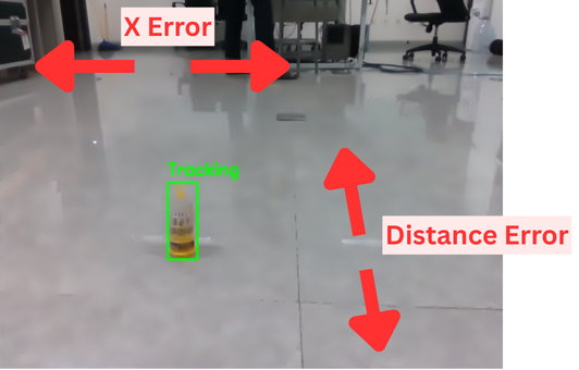
Figure 4: Robot performing the grasping action. The robotic arm executes the grasp based on the filtered optimal grasp pose.
Failure Case Analysis
In the failed trials, specific challenges were identified based on object characteristics and grasping conditions. In trial 5, the grasp attempt on the golf ball failed because the ball slipped during grasping — its spherical shape provided less surface stability compared to the box-shaped charger, making it prone to slipping. In trial 8, grasping failed when the golf ball rolled away after being slightly nudged by the gripper, again highlighting the inherent difficulty of handling spherical objects that do not remain stationary when disturbed. In trial 11, the grasping failure occurred with the battery, which is heavier than the other tested objects — the improper grasp force was insufficient to stably hold it. These failure cases provide clear directions for future improvement: force-sensing grippers, adaptive grasp force control, and specialized strategies for small/spherical objects.
Limitations and Future Directions
Limitation 1: Insufficient adaptability to object shape and size. The system achieves only a 50% success rate for spherical objects (e.g., golf balls), as the current gripper lacks sufficient friction and envelopment to stably grasp curved surfaces. For heavier objects (e.g., batteries), the gripper's payload capacity also becomes a bottleneck, limiting the system's generality across diverse object scenarios.
Limitation 2: Lack of force feedback in grasp control. The current system uses open-loop grasp force — the gripper closes with a preset force without real-time adjustment based on object weight and material. This leads to unstable grasping of heavy objects and excessive force on light objects. Introducing force/tactile sensors for closed-loop force control would significantly improve grasping reliability.
Limitation 3: High requirement for environmental structure. Navigation and mapping rely on LiDAR performance in structured indoor environments; adaptability to highly dynamic or unstructured environments (e.g., outdoor, cluttered scenes) has not been verified. YOLOv8n detection accuracy is also affected by lighting and occlusion conditions.
Future work directions include: integrating force/tactile sensors for closed-loop grasp force control, expanding the object detection model to support more categories and materials, exploring learning-based adaptive grasping strategies to replace the fixed three-stage filtering, and validating system robustness in more diverse real-world scenarios.
Conclusion
This paper presents a task-level interaction system for autonomous grasping on a quadruped robot. Through hardware integration (Lite3 + OpenManipulator-X + Jetson Orin NX), a layered ROS architecture, and a finite state machine, the system autonomously decomposes the operator's high-level task commands (room selection, object clicking) into a complete pipeline of navigation, detection, tracking, grasp planning, and execution. Key technical contributions include: a GraspNet-based three-stage filtering strategy (confidence score → distance to center → orientation adjustment) ensuring the selection of the optimal feasible grasp pose; coordinate frame transformation accurately mapping grasp poses from the camera frame to the robot base frame; and a PID controller combined with a CSRT tracker for reliable approach motion. The 75% success rate across 12 real-world trials validates the system's effectiveness, while failure cases reveal improvement areas in object shape adaptability and force feedback control. This work demonstrates the potential of quadruped robots as service robots performing physical interaction tasks in real-world environments, laying the foundation for future applications in more complex scenarios.
SOURCE LINKS